Tel: +86-13713989501
Email: info@camtechcircuits.com
1. Manufacturing process
Before starting HDI PCB design, you need to understand HDI manufacturing process parameters first. To do this, you need to consider three factors:
◈ Aperture Ratio
If you do not know the aperture ratio to be used for manufacturing, you cannot successfully build HDI PCB. However, the general rule of thumb is to use smaller apertures for thicker boards, and vice versa.
◈ Stack
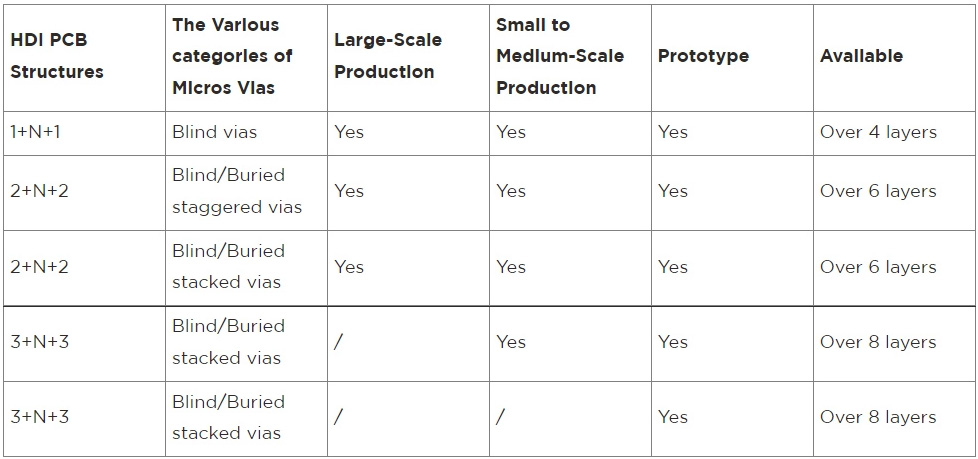
The stack of HDI PCB must be classified according to blind hole and sequence. Therefore, the stack has four different categories; Non laminated 2-HDI (with buried holes), laminated 1-HDI (with buried holes), laminated and resin filled 2-HDI, and laminated and non resin filled 2-HDI.
◈ Technological process
There are some processes. But the main ones are four layers of HDI stacked in one layer and six layers of HDI stacked in two layers. These processes are somewhat similar to the standard PCB process for drilling sequencing.
2. Layout
Typically, HDI PCB layouts have high density. Therefore, it is necessary to ensure their maintainability, weldability and instability.
3. Tracking
You must consider the tracking process, including the consistency of the tracking, the minimum line width, and the adjustment of the safety spacing
Number of layer | 1 - 32 |
Production time | 1 day - 4 weeks |
Quality grade | Standard IPC 2 |
Order quantity | 1pc - 10000+pcs |
Copper weight (finished product) | 6 oz/10 oz |
Plate size | Minimum 50 * 50mm | maximum 450 * 406mm |
Material | FR4 standard Tg 140 ° C, FR4 high Tg 170 ° C, FR4 and Rogers composite laminate |
Board thickness | 0.2mm - 10mm |
Silk screen color | White, black, yellow |
Color of solder mask | Green, black, blue, white, red, yellow |
Minimum tracking/spacing | 2.5mil/2.5mil |
Solder resistance layer | According to the file |
Silk screen surface | According to the file |
Maximum index of blind hole/buried hole | 3-layer stacked via interconnection, 4-layer staggered via interconnection |
Minimum ring | 4mil, 3mil - laser drilling |
Other methods | Rigid flexible combination Via In Pad Buried Capacitor (only applicable to Prototype PCB total area ≤ 1m ²) |
Surface treatment | HASL - hot air leveling lead-free HASL - RoHS ENIG - electroless nickel plating/gold deposition - RoHS silver deposition - RoHS tin deposition - RoHS OSP - organic solderability preservative - RoHS |
Minimum drilling diameter | 6mil, 4mil - laser drilling |

From the appearance, HDI PCB is creating many possibilities for all walks of life. It can only develop over time.
Therefore, this is a technology you should consider -- especially if you need some technology that can save time and improve efficiency. In addition, the demand for HDI PCB increases regularly. Therefore, we can say that it is very promising. Are you interested in learning more about HDI PCB?
◈ What is the difference between standard PCB and HDI PCB?
The standard PCB uses through holes. Therefore, they have high stray capacitance and huge impedance discontinuity. In other words, standard PCB has good signal integrity performance.
However, HDI uses buried holes and small blinds. Therefore, it reduces stray inductance and capacitance. In addition, it provides excellent signal integrity performance. Other important differences between standard and HDI PCB include:
● Through hole PCB (standard): low component density per square inch
● HDI PCB: Compared with standard PCB, HDI has higher component density per square inch
● Standard PCB uses mechanical drilling
● HDI uses direct laser drilling
● Standard PCB has heavier and larger circuit board
● HDI has lighter and smaller boards with more functions
● Standard PCB has a large number of layers
● Few HDI layers
● Standard PCB uses through hole
● HDI uses micropores, blind holes and buried holes
● When standard PCB is paired with low-key package, it faces some compatibility problems
● HDI perfectly matches with low pitch package and high pin count
◈ HDI PCB application
● Automobile industry
Technology drives the automotive industry towards several goals.
They help improve the driving experience and save vehicle space. That said, it is not surprising that manufacturers insist on using small PCB (HDI) to achieve this goal.
● Healthcare sector
HDI PCB reveals many possibilities in the medical field. After all, the human development index plays an important role in diagnosing diseases. A good example of a medical device or device that uses HDI is a pacemaker.
● Consumer Electronics Industry
Your consumer devices are actually part of you. Therefore, whether it's your VR headset, tablet (touch screen device), smart watch (wearable technology), personal computer/laptop (laptop), entertainment system, smart phone (mobile device) or household appliances, all these gadgets have an HDI. In addition, HDI is responsible for the outstanding functions you enjoy from your electronic devices. In addition, HDI PCB promotes portability. For example, HDI PCB helps to produce compact electronic products. However, as a manufacturer, it is important to observe the regulations carefully. In this way, you will avoid creating designs that affect the quality of the equipment.
● Industry
Except that HDI PCB can withstand extreme conditions, they consume less energy. When this happens, it produces the maximum output. This is why this kind of PCB is very useful in industry. You can find HDI PCB in industrial equipment such as electric drill.
What Services Do You Provide?
Can I Get The Stack Diagrams From You?
Do You Offer Any Discounts?
Can I View And Process Altium CAD Data Directly?
What If I Am Not Satisfied With Camtech PCB?
What Else Should Be Considered When Manufacturing HDI PCB?